New
power-plant
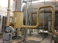
Gas Separators/Filters
i. Skid mounted gas separator/filter unit shall be
supplied to remove asphalt sand, wax material, and other gas bore contaminants
(black powder) having a particle size of 3 microns and larger as well as liquid
hydrocarbons and water, as per the applicable Saudi Aramco standards.
The gas separator/filter unit shall consist
of four (4) separators (three in service and one standby) complete with
interconnecting piping, valves, and instruments.
The skid arrangement shall be
designed to allow separators to normally run in parallel or independently when
one or more separator/filter(s) is out of service for maintenance.
ii) It is pertinent to note that the Owner is
facing the problem of excessive black powder collected at the filtration units
of some existing plants, so the bidders shall give special emphasis on the
design of filter separators to cater to this problem.
iii. In this regard, the bidders shall submit a
detailed report with their proposals
about the remedial measures to be built in the design of the filter
separators, in order to take care of the excessive black powder problem.
iv. The salient design parameters shall be:
1) Design
Conditions:
1st Pressure Max. - 1060
psi (73 bar)
Min. - 7.5
psi (vacuum)
) (0.5
bar, vacuum)
2nd Temperature - 200F (93 C)
3rd Min. Design Metal Temp. - 20F (-6.66 C)
4th Design Code - ASME Section VIII Div. I
5th Corrosion Allowance 2 - 3mm
Operating
Conditions:
1st Service - Natural Gas
2nd Pressure - Minimum 450 PSIG, (31 bar), maximum
770 PSI (53 bar)
3rd Temperature - Minimum 32F, (0C) maximum 130F (50C)
4th Flow rate - As per fuel gas requirement considering
three separators
in
service and one standby.
5th Efficiency - 98% of all liquid droplets and
entrained
solid particles of 3
microns
size and larger
Scraping Facilities a] Scraper Traps
i. A permanent scraper station shall be installed on
the pipeline, as periodic scraping is required for corrosion control of the
pipeline, and removal of solid & liquid build-up in the gas line.
ii. The term "scraper" includes all
devices for internal cleaning, gauging, inspection (instrumented tools),
batching, and inflatable spheres.
The
term "traps" refers to the devices used for launching or receiving
the scrapers.
iii. Scrapping facilities comprising one (1) scraper
station at each end, capable of launching/ receiving instrumented scrapers with
related facilities including all valves, instrumented scrapers, passage
indicators, etc. shall be provided for the pipeline.
iv. The scraper launcher shall be installed at the
beginning of the pipeline near the tie-in point
b] Design Requirements
i. Scraper traps
ii. Scraper trap station piping for onstream
scraping operations shall be provided in compliance
iii. Scraper Stations shall be provided in
accordance:
1)Full bore
isolation valves of the same nominal size as the pipeline at both ends.
2) A barred tee in
the mainline near each scraper station.
3) A bypass line,
between the tie line valve and the trap, with a kicker valve and a second block
valve to provide tight shut-off in the bypass line.
4) A blinded valve
for the hydro test.
5) A double-valved
drain system sized to permit drainage of the trap.
6) A vent system
to provide safe disposal of gas and vapors through burn pit/flare before the
trap closure is opened.
7) A purge
connection on scraper launcher as well as receiver
8) Sample
connections.
9) A pressure
gauge near the trap closure and one on the mainline near the trap isolation
valve
10) A flush
connection each on scraper launcher and receiver. end, potable water
shall be tapped from facilities through a permanent connection whereas the provision shall be made for hook up with a tanker truck.
iv. Scraper passage indicators
v. The proposed pipeline shall not have valves,
fittings or connections installed, that may impede the travel of the scraper.
vi. Scraper traps shall be provided with tight
sealing end closures and locking mechanism of the closure shall be of the
clamp-ring or band lock type.
vii. The closure locking mechanism shall be provided
with a pressure warning safety interlock device, which must be opened before
the closure mechanism can be unlocked.
Closing of the pressure warning safety interlock shall not be possible
until the closure locking mechanism is fully engaged and locked.
viii. All closure doors shall be supported by
adjustable hinges or an adjustable davit.
ix. The required clearance area for the door shall
be indicated by the Contractor.
x., In order to provide mechanical assistance to
break the seal when opening the door and compress the seal when closing the
door, all required tools shall be included in the delivery and suitable
attachment lugs for the tools shall be provided where necessary.
xi. Platforms shall be provided for easy access to
valve actuators and closure operating mechanism. All valves shall be accessible at least from
one side of the trap.
xii. A mechanical scraper-loading device with a suitable lift and span shall be provided to assist in the loading and the
receiving normal cleaning and batching scrapers.


No comments:
Post a Comment